Hit Buffer switches and jumpers settings
HB : back to Hit Buffer's page.
HOME : back
to Stefano Belforte's home page
The Hit Buffer has a small set of hardware controls that
need to be properly set in order to use the board.
There is one set of
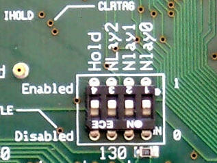
jumpers, and two dip-switches blocks,
"control switches" and
"VME switches".
The following image indicates their location on the board.
Clicking on their names in the following list will bring up
close up pictures.

Best thing for you is to forget immediately and forever about jumpers
and VME switches.
For control switches you normally forget about
them until you have to run some special test on the Hit Buffer that
instructs you to use them.
Proper settings are as follows:
- control switches
-
- jumpers
-
BEWARE: Hit Buffer #19 and #20 need special settings. See below.
These jumpers are used to fine tune clock distribution to the Xilinx
chips by changing their skew times. Misplaced jumpers means the
board fails in strange ways. Jumper settings is to be changed
(with care and understanding by experts only) if board operating
frequency is changed.
Never touch them unless Stefano told you to do it.
If in doubt, make sure they are in the following
configuration
(good for 20MHz clock) :
3, and only 3, jumpers must be plugged in:
U67 none
U65 4F0 Vcc (bottom)
U64 none
U66 4F1 Gnd (top)  4F0 Vcc(bottom)

       U67       U65      U64      U66
gnd  .......  .........  .....  x........
vcc  .......  .x.......  .....  .x.......
With jumpers properly set, roboclocks working, and a 20 MHz quartz,
the 3 clock test points on the lower right of the Hit Buffer, should
yield
this picture
on a scope. Traces top-to-bottom are: CLK - NCLK (not clock) - DNCLK
(double not clock i.e. NCLK multiplied by two in frequency). They look
not aligned in phase, but this is what they should be. With reference
to CLK the trailing edge of NCLK is at -2.5 nsec, the trailing edge
of DNCLK should be in phase with NCLK, again about -2.5 nsec before the
rise of CLK.
For more information on HB clock timing, see the
HB timing page.
 May 2002: settings for Hit Buffer #19 and #20
Hit Buffers #19 and #20 have been assembled 2 years later with same PCB
and components. But need slightly different timing. Only 2 jumpers total
must placed as indicated below (only difference in on U66: 4F1 to mid
4F0 to gnd):
       U67       U65      U64      U66
gnd  .......  .........  .....  .x.......
vcc  .......  .x.......  .....  .........
- VME switches
- These are used if the HB is put in a non-VME64 crate with
no geographical address.
Never touch them unless Stefano told you to do it.
If in doubt, make sure all of them are to the left (Vcc-0),
just as in the picture.
stefano.belforte@ts.infn.it